|
|
|
Previous Revisions of my Pulse Discharge Machine
Experiments - (Amusing stuff to do with 50-100 KA)
Shrinking Coins (all pics are "Clickable" for larger image)
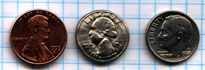 Shrunken quarter compared to a penny and a dime |
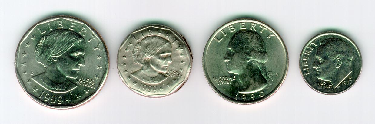 Shrunken Susan B. Anthony Dollar |
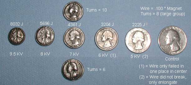
Here are the latest quarter
experiments.
This clearly shows that 10 turns works better than 6 or 8. The next
experiment needs to be to keep the energy level constant and vary the number of
turns until an optimal number is found. The equations show that it should
be an "upside down" parabola sort of thing with a definate maximum.
I was actually half-way scientific about it this time. I always intend to
be, but I wind up just blowing something up, laughing maniacally, blowing up
something else, laughing, etc...
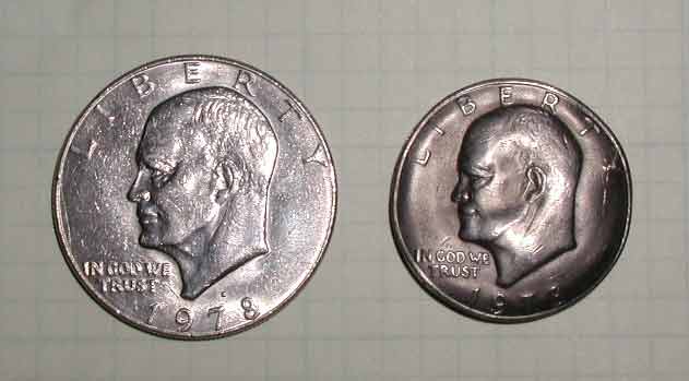
Results of 10KV, 12T of 10ga magnet wire. Lots of out of plane
deformation (cupping) of the silver dollar.
Crimping Tubing (Demonstation of Magnaforming, an actual industrial process!)
 |
 Notice how annealing allowed the metal to deform without cracking |
 High energy levels caused the unannealed pipe to split and wrinkle |
Blowing stuff up (a man can't just sit around not knowing what would happen...)
My own special recipe! I call it "Seven Kilojoule Apple
Delight!"
| Bert Hickman's Telsa & Pulsed Power Page | Excellent hobbyist site with lots of good photos and theory. Be sure to read the theory of quarter crushing. It's the best description that I have found. Bert is the most knowledgeable pulse power hobbyist out there. His links cover it all - go see Bert's links |
| Electromagnetic and Hyperplastic Forming | THE premier resource for High Velocity Metalforming with Pulsed Magnetic Fields. A MUST READ. |
| Robert Stephen's Quarter | Picture and info on a crushed quarter |
| R.E. Beverly III and Associates | Pulsed Power Components and Systems, Research and Development, and Scientific Software. Commercial site that contains great technical articles on triggered spark gaps. Nice pictures of trigatrons. |
| Jim Lux's Web Page | Great site with lots of HV information. Be sure to check out the HV handbook that Jim is working on. |
| MIT's Corridor Lab Exploding Wire Demo | Nice little exploding wire demo with oscilloscope analysis |
| Bill the ArcStarter's "Big Capacitor" Page | Bill & Fleishwulf performed and documented several excellent pulse dicharge experiments. Be sure to crawl around in this site and visit the can crusher page, quarter shrinker page, cap autopsy, and the photomicrographs of the shrunken quarter on Fleishwulf's page |
THANK YOU:
- Jim Lux
- Bert Hickman
- Moderators of Telsa Coil Mailing List and High Voltage List
Charging and discharging a large pulse capacitor into a load is not a trivial process. There are an infinite number of possibilities that range from simple HV switches involving banana plugs with PVC handles to complicated and expensive HV relays and triggered spark gaps. The following schematic and text describe an optimal system arrived at after several years of iterations and refinements. I
1) FULL WAVE RECTIFIER WITH TRIGATRON
NOTE TO SELF - MAKE A NEW SCHEMATIC INCLUDING VAC CONTACTORS
NOTE - the following is a bit out of date. I'm working on the revision.
The trigatron is complete and all
components are ready to go. See description of trigatron electrical
components below. Here is a breakdown of the charging and pulse
circuit. (Note, ignore polarity of caps - I was in a bit of a hurry and
didn't have time to draw them correctly)
R1 = 5K, used to limit current back into charging circuit.
S2 = actually my TC controller with deadman switch
S3 = wired a relay in parallel with my deadman. This switch opens when I
release my deadman. Actually, I will probably wire it so that it shorts my
charging circuit to ground when it opens. This will provide some
additional protection.
C4 = 178uF, 10KV Sangamo pulse cap
C2, C3 = 30KV, 500pF doorknob caps used to prevent any HVDC from getting back
into trigatron trigger circuit
Work Coil = recommended coil for a quarter crusher is 10T of 10ga magnet wire.
2) SWITCHING HV AT LOW CURRENTS
standard relays
submerged in HV oil
- high contact resistance, messy, gets the job done on a low budget and time
constraints!
|
Vacuum contactors PDF datasheet for my vac
contactors RF10B Gas Filled Contactors |
High Voltage
Relay |
3) INEXPENSIVE HOMEBREW HV DC VOLTMETER
|
|
Find any old meter
that has a full scale (fs) reading of 50 or 100uA. Now for a bit of Ohm's
Law. Lets say that you want your 100uA meter to read 10KV fs, lets
calculate how much series resistance we need to get 100uA. V=IR, so R =
V/I = 10e3/100e-6 = 100 meg ohm. Easy you say, those only cost about 69
cents down at Radio Shack. Well, it's almost that simple... A normal
1/4 watt resistor can only handle about 1kV before the voltage will simply run
across the outer surface of the resistor rather than through it. With this
in mind, we quickly see that we will need at least 10 resistors in series.
This means that you should go get yourself a bunch of 10meg 1/4 watt resistors
and heat up the soldering iron. I typically solder about 9 of them
together, measure the resistance with the best meter that I can get my hands on,
and then fine tune the overall resistance with smaller resistors. Have fun
photo is "clickable" Note - this thing recently started acting crazy. I haven't done any troubleshooting yet because I found a Fluke 6KV high voltage probe for my DMM. It works great all the way up to 10KV with no problems. I like seeing the trend from the analog meter better but the DMM solution is more accurate and easier to see from a distance. |
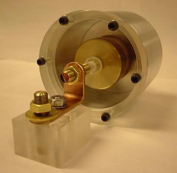
4) SWITCHING HV AT HIGH CURRENTS (TRIGATRON)
TRIGATRON MECHANICAL COMPONENTS
Here are some pictures of the
mechanical components of a home made trigatron fabricated by Brian Basura.
All images are "clickable" for a larger view.
 See description below |
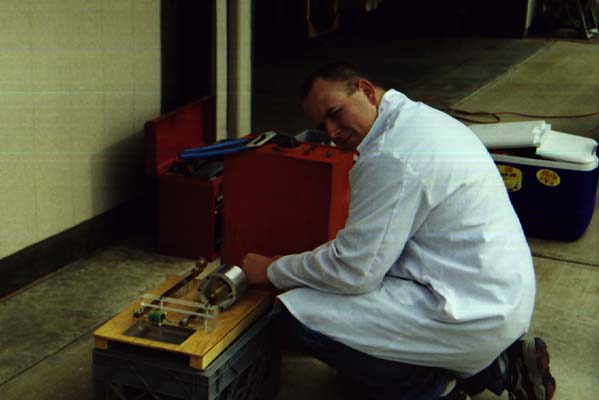 Ross is giving it one final checkout |
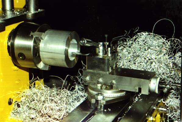 Trigatron housings aren't easy to build on a small lathe! |
 Clear End |
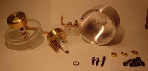 Dissasembled View |
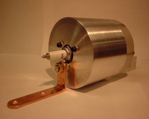 Spark Plug End |
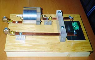
This is the prototype trigatron base and bus bar
configuration. The pulse cap hooks up via the 2ga screw down connectors on
the left and the quarter goes inside the coil on the right hand side of the
photo. This is the 2nd of 2 units that Brian Basura fabricated (as usual,
beautiful craftmanship!) Turns out that the blast force was much beyond
what we anticipated. Extensive damage was done to the blast plate, wooden
base, and 1" thick lexan base when the diamond plate containment box was
fitted over the quarter shrinking coil and the fire button was pushed!
Regardless, with a little last minute engineering we managed to make this unit
hold up for 8 or 9 quarter shots.
Notes on firing voltages:
I disassembled and cleaned my trigatron for the first time on 2/16/01. I am
pleased to report that there was no significant wear and only minor corrosion of
the aluminum and copper surfaces. The plastic liner was discolored from
the extreme UV produced by the main arc. The trigatron had about 60 shots
on it before the cleaning. I had to readjust the spark gap upon
reassembly. I screwed the electrodes together until they touched and
started backing them apart. The results are as follows:
2.25T - self triggered at 7KV
3.25T worked great up to 10KV and would still reliably fire at
5KV.
4T would still fire at 5KV but self triggered at 10KV after a few shots (the
clean surface of the electrodes no doubt became bumpy from minute amounts of
copper vaporizing and condensing back on the electrodes). I still need to
increase the distance to have safe functionality up to 10KV.
TRIGATRON ELECTRICAL COMPONENTS
The trigatron is triggered by a high voltage arc inside of the main body. We are using a modified spark plug as the trigger electrode. The following circuits are various schemes to produce an arc on the modified spark plug.
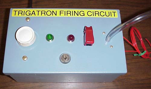
Method 1 - Light dimmer module (using a
phase angle fired SCR)
This method was recommended by Bert Hickman. It is simple,
inexpensive, and will produce about 1" arcs from either a standard
ignition coil or a HEI coil. The light dimmer can be found at Home
Depot. My model is a $3, 600W Lutron. The capacitor is an oil
filled motor run capacitor.
 |
 |
 |
| Schematic | I have both a phuematic fire switch and a push button switch wired in parallel. I only use the push button for bench testing! |
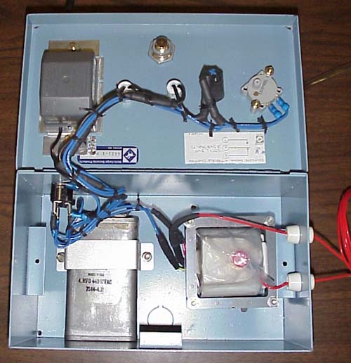
Here is a nice shot of the inside of the box. |
Method 2 - One shot SCR circuit
This design uses a voltage doubler to charge C2 up to about 300VDC.
When S1 is depressed, the SCR turns on and dumps C2 across the primary of
the ignition coil. The approx 100:1 step up ration turns the 300V into
about 30KV. This produces and arc of about 1/2 inch on a standard
ignition coil or about 3/4 inch on a HEI. Bert Hickman reports that he
continous nature of the "light dimmer" circuit is very helpful in
igniting the trigatron at lower voltages. It will be interesting to
test the effectiveness of this one-shot circuit.
Sizing the components:
C1 is an oil filled motor run capacitor. Electrolythics can't tolerate the AC and will rapidly fail.
D1 & D2 are simple 1N4007 diodes good for 1KV, 1A.
R1 is sized so that it limits the current to the SCR to below the cut-off current
C2 is a 1uF, 400V electrolythic. I tried larger caps here but didn't see any dramatic improvement in performance
The ignition coil is a $15 standard ignition coil or a cheap $11 HEI coil. The HEI coil is smaller and produces a "hotter" arc
Specs on a typical 6A, 400V, SCR that I picked up at Radio
Shack
DC Gate Trigger Current: Typ 12ma.
On-State Current, Tc=80C 6A (RMS) (max)
Repetitive Peak Off-State and Peak Reverse Voltage: 6ma (max)
Peak Reverse Gate Voltage 10V (max)
Peak Gate Power Dissipation: (300 sec pulse) 5W (max)
Ave Gate Power Dissipation: 0.5W (max)
Notes on Ignition Coils
After fooling around with several types of ignition coils, I decided that I like HEI coils best. They are smaller and have a higher turns ratio. I tested the turns ratio by applying a sinusoidal voltage to the input using a HP signal generator and I scoped both the input and output waveforms on a Tektronics TDS210. I set the input for 1 volt and simply read the output voltage. The results were the same when measuring peak-to-peak and measuring RMS voltages. I used an aftermarket HEI coil for a 76 Cadillac with a 500 cid engine. It cost about $12 at Kragen. This ignition coil is nifty since it is the same one that Terry Fritz modified to turn it into a mini Tesla Coil. Terry managed 13+ inch arcs off this baby. (need to link to Terry's GMHEICSLR work here)
Standard
Coil has a turns ratio of about 66
HEI has a turns ratio of 84V
Charge on Capacitor vs. Stored Energy
 |
VOLTS | ENERGY (Joules) |
| 0 | 0 | |
| 1000 | 89 | |
| 2000 | 356 | |
| 3000 | 801 | |
| 4000 | 1424 | |
| 5000 | 2225 | |
| 6000 | 3204 | |
| 7000 | 4361 | |
| 8000 | 5696 | |
| 9000 | 7209 | |
| 10000 | 8900 |
Table valid for a 178uF capacitor
Energy (J) =
1/2*Capacitance*Voltage^2
|
|
These
things will kill ya! |
|
[Back to top | Tesla Page | Contact Ross ]