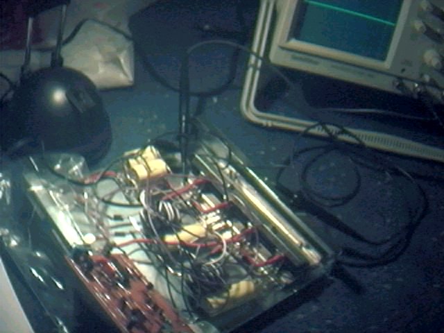
Above is my prototype SSTC MK1 control (vero board at bottom ) and driver stage (the wire mess bit ).
The design here was built with helpful advice from Richie and his SSTC design. Richies control stage can be found here http://www.richieburnett.co.uk/sstc01.gif and the driver stage here http://www.richieburnett.co.uk/sstc02.gif
The driver managed to give about 2" arcs with around 70VDC input. Not much power for the input voltage but it proved to work. The first test run was done with a unsmoothed supply. The arcs looked very aggressive and looked like sharp knives. A audible hum was noticed in operation.
The second test was done with a smoothed supply, 2 Smoothing caps made up a value of 0.5F 150VDC. The arcs were around 1" in length and very bushy. A quiet hiss was noted in this test.
In all tests with this driver I used a secondary coil which was wound upon a 6.3"dia form 17". Coils resonant frequency was measured to be 109khz. The primary in these tests was about 20turns of 30amp stranded cable wound directly ontop of the secondary. While over around 50VDC input it was noticed that corona was starting to form around the primary. A clear case that the insulation was not upto the job. Latter that day the SSTC Driver blew up and I found 2 of the Driver FET's had died. I would imagine the corona was shorting the primary out and spiking it which finally killed the FET's.
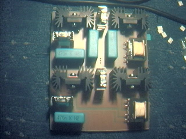
A couple of weeks of design work and I built the Driver board as shown above. This gave way for some changes to Richies original design though still very much the same design. The 4 220nF capacitors were replaced with 2 470nF. No real reason for this but it saved on board space. These caps are the 2 vertical ones near the top of the board. The horizontal capacitors are the 470nF smoothing caps. There is plenty of space left to place a larger value in there for any reason.
The Mosfets used here were STW20NB50 ( 20amp 500V ). The Zener diodes are mounted just in front of each Mosfet, they are hard to see in the image but they are there. I used BZX85C15 for all zeners on the board. Schottky diodes were replaced with 8TQ100 ( TO220 mount). I still used the MUR1660 rectifier diodes, also TO220 mount.
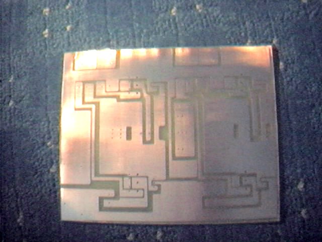
A lot of thought went into the layout and design of the board. I did several revisions of the board before I decided to etch out the one you see now. All tracks are short and very thick. All diodes are connected very close to the Mosfets. The MUR1660 diodes are mounted on the reverse side of the heatsink where the Main driver Mosfets are mounted. They are connected directly and so the actual track length is only a few mm at most. The 4 black heatsinks all have the STW20NB50 mounted on the front and the MUR1660 mounted on the rear. They are of course totally insulated from each other and the heatsink itself. The 4 silver type heatsinks hold the Schottky diodes. These heatsinks are probably not needed though I added them in there since I had some spare space on the board anyway.
The 2 small transformers on the right of the board were added at the suggestion of Jan Wagner. These transformers are on a 1:1:1 ratio and make them ideal to replace Richies wound transformers. These transformers are rated to be used at high frequency such as 250Khz and up and work very well.
I tested the board first of all out on my scope with the original MK1 control board. I found a fault in my design where 2 of the secondary windings were crossed over. This had a easy solution of some minor track editing on the back of the board. Luckily the small reroute was simple to do. In all the excitement of building the board I managed to forget to add some discharge resistors across the 470nF smoothing caps. Not too much of a problem in anycase.
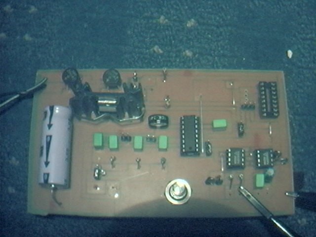
Above is the MK2 Control board during initial scope testing. This Design is basically Richies TL494 design with a few changes. Firstly the oscillator resistor and capacitor network had a few mods to it. I added in there a row of 3 100pF capacitors with jump links so I can add or take off values. I also added in a row of selectable resistors which are 1K,10K and 100K. This enables me to have a wide selection of frequencies so I can try out more coil variations.The Variable resistor is a 50K 10 turn precession pot. It is drilled and screened though the main ground track on the PCB.
The Second change was suggested by Richie to use the TC4421/22 IC's ( bottom right ). These replace the ZTX450/550 transistors from richies control stage. There are 2 packages of these drivers a TO220 type and the IC version. The IC version is rated at 1.6W and the TO220 type was around 8W. I used the IC version since it was easier to design the board with these.
The last additional change came from Jan Wagner's design for a auto tune design which can be found here http://www.hut.fi/~jwagner/teslaschem/selfreso-schematic.gif . Jan's design is based around the 4046IC and needs very few external parts to operate. Jan's design uses a 555 for a interrupter and a kick start for the auto tune. The need for a kick start was that when the power was first switched on there was no feedback to start with so a kick was needed to set things in motion. With my board I found a square wave on the output of the IC anyway which seems to be enough to kickstart the coil into operation.
Since I already had the TL494 on the board I used this inplace of Jan's 555 IC. I also added in a interrupter just the same though I was able to discard the 4001 IC in Jan's design for a single transistor. I haven't yet used this function on my board yet since it starts up on its own anyway. My guess is that the 4046 maybe slightly coupled to the AC in supply rail via capacitance in the tracks and maybe enough to set the IC to oscillate. I suppose a badly designed board has its advantages ;)
The selectable frequency range for manual tune is as follows. All frequencies are in khz.
| RESISTOR | CAPACITOR | START FREQ. | END FREQ. |
| 100K | 300pF | 27 | 39 |
| 100K | 200pF | 38 | 56 |
| 100K | 100pF | 68 | 98 |
| 10K | 300pF | 62 | 294 |
| 10K | 200pF | 88 | 391 |
| 10K | 100pF | 155 | 592 |
| 1K | 300pF | 74 | 102 |
| 1K | 200pF | 102 | 1147 |
| 1K | 100pF | 180 | 1180 |
You can see from the table that I can get a very wide range of frequencies from as low as 27khz right up to and over 1mhz. from the top of the table I can tune in very fine with my 50K variable pot from 27khz to 39khz. I can also gain fine tuning for others also. I also can have a wide sweep from 180khz to 1180khz. All these combinations should alow me to use whatever coil and do what ever tests I like without every having to redesign the board. It was also good to see the TL494 ran at such a high frequency also!
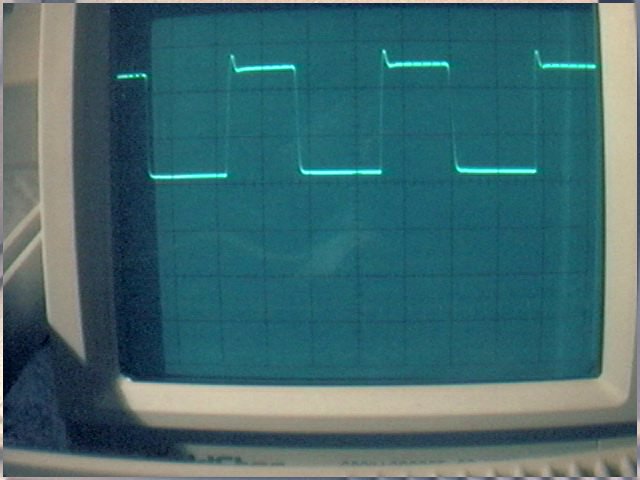
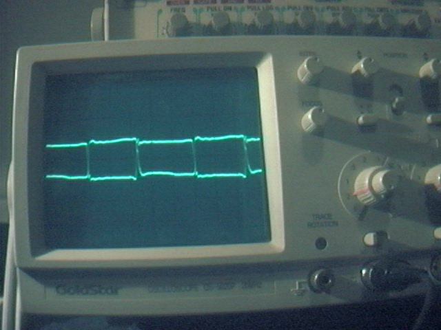
All the waveforms I took looked very odd indeed. This really puzzled me for a while and I couldn't seem to work out why I was getting these distorted waves. The Source of them came from the TL494 and was a perfect squarewave. This wave was taken from the output of the TC4421 driver IC. After a lot of thinking and tinkering I was near giving up. No matter what I did I couldn't get a nice squarewave out of the board. I wasn't going to try running any real power through it until I could track down this fault.
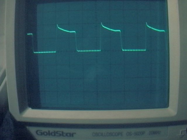
After chatting to Jan he suggested it maybe a problem with the smoothing for the supply for the IC's. Ah-ha! The Euro dropped and it all came into light. I realized I hadn't any smoothing on the board at all! A few cap additions latter and I got the following wave...
This wave was looking more like what it was supposed to be looking like. The small spike on the rise of the wave was eventually smoothed out with more supply smoothing.
Finally...
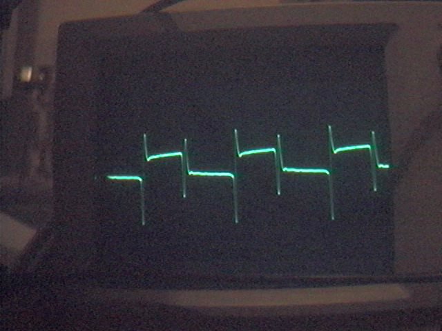
The main Driver output waveform. After some adjustments and tinkering I managed to get this wave looking a lot better. One reason was the duty cycle was slightly off. This not only effected the pulse time of each cycle though also effected the voltage differences as seen in the image. The final wave was pretty much perfect and whole lot better than the one shown.
You can also see that there is a small dead time between each cycle. This is a good feature of the TL494 since its actual duty cycle is only around 45%. This ensures a small delay between on and off cycles for the mosfet bridge.
During actual use the heatsinks dont even get warm. I have only ran upto around 40VDC which isn't a great voltage though it is good to see there is no heat on them.
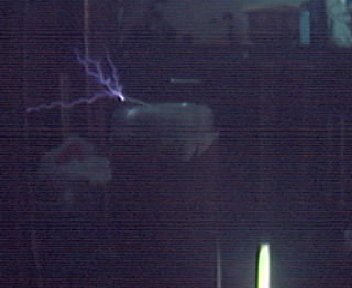 Click image for a small movie of the running coil.
This small movie was taken on February 16, 2003. This was the first running test of the new MK2 control board and MK4 driver board. Movie was taken with a cheap webcam so the quality is not to great, sorry :(
To the left of the image was a length of M10 studding which was grounded at the bottom to give a strike point. This was about 6" from the top of the toroid. A small bolt was used for a quick breakout point. The tube lighted behind was a 12" flo tube just used as a indicator for the tuning point. Voltage input to the driver was around 60VDC. I ran upto 70VDC though its blowing 3amp fuses. It could be I need some AS types or there maybe some other reason for them blowing.
One thing to be careful of is that the tuning is hard work since everytime you move near the coil it goes off frequency. I was testing this out by moving my hand near the coil. Rather stupid really since I got hit by a 3" arc from the coil! No harm was done ( thankfully ) apart from the small of burning flesh in the room :-\
On this run I also switched over to Jan's auto tune design. This seems to work ok though I have noticed a few things which are not yet explained. Firstly I haven't yet used a coil around the secondary for feedback. I first tried a length of wire near the coil though this didn't work at all. I then tried a small square of metal around 4" square and this worked. The output power seems to have dropped by around 20% and the flo-tube also is a fraction dimmer. Placing my had near the coil again detunes the coil. I expect that this is due to the fact that I have not yet used the interrupter.
It seems that the 4046 locks on the first initial frequency and holds at that point. In this case the 4046 needs to be reset probably around 1khz which Jan suggested a while ago. I will test this idea out when I finish the control board and will post more on this in a few days.
RECENT WORK
February 18, 2003 - First attempts in audio modulation HERE
February 19, 2003 - Primary breakdown and tests HERE
February 20, 2003 - First Current draw tests HERE
May 25, 2003 - June 15, 2003 - New heatsinks added and more test runs - gate driver thoughts and tests HERE
November 3, 2003 - MK5 SSTC built and almost ready for testing! Click HERE
Soon to come soon....
My revised SSTC design......Audio modulation... More tests and results to come soon! Stay tuned! ;-)
If you find any errors in any of these pages then please let me know. If you can suggest anything or improve on anything then please do let me know. I am new to the SSTC scene and I hope to share my tests and results as I do them over the comming weeks. I will update all these pages as I do more tests.
Links
Jan Wagner's Self-resonant solid state teslacoil http://www.hut.fi/~jwagner/teslaselfreso-sstc-demo.htm
Richie Burnett SSTC http://www.richieburnett.co.uk/sstate.html
John Freau's quality spun aluminum toroids http://hometown.aol.com/futuret/page1.html