|
|
|
| The
Tesla Coil Builders of Ft. Worth was founded in 1994 by Bert Pool and Bill
Emery. The club had grown to include 5 core members that routinely meet
to discuss projects of interesting to the High Voltage Amatuer
Scientist. I've been fortunate enough to hang out with the TCBFW
team,
learn many new things, and play with their amazing gear. I've attempted to
document my visits in the following page. It's my hope, as well as the
hope of the TCBFW, that this page will play a small role in inspiring
others to learn more about the hobby that has taught us so much given us much joy.
Note - All Images are clickable for a larger (800x600)
size image. |
|
|
|
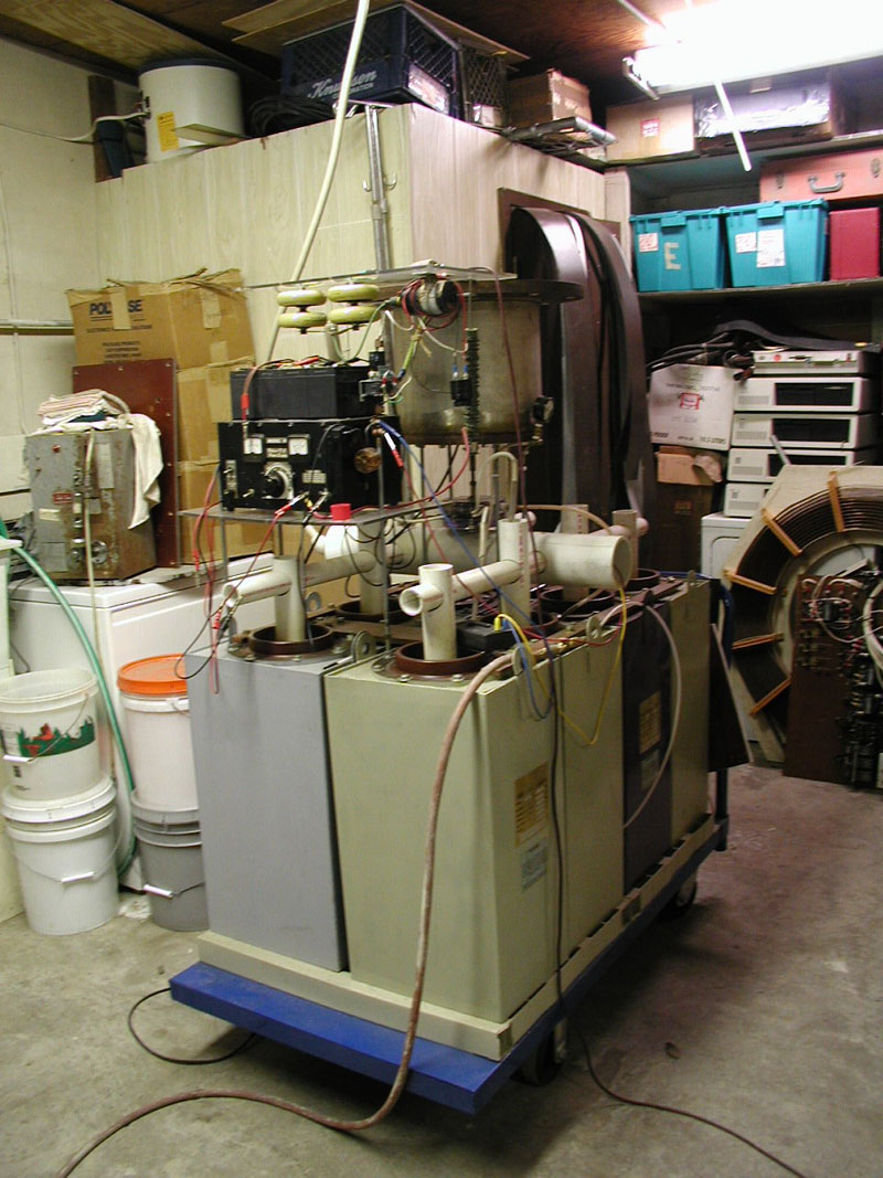
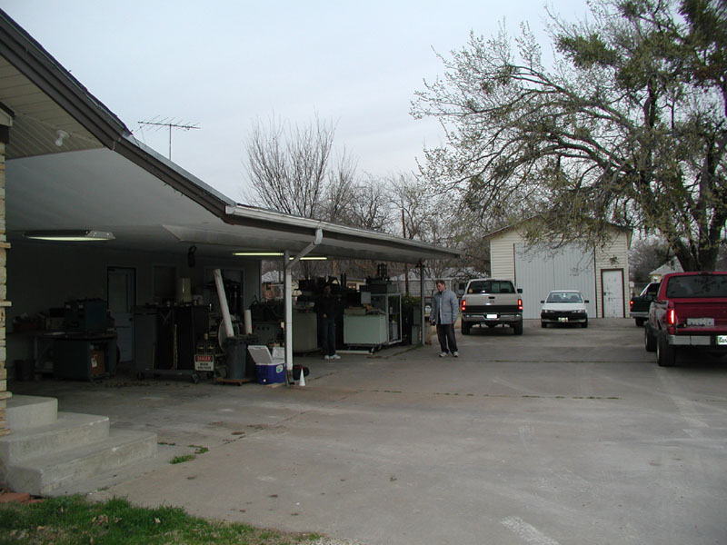
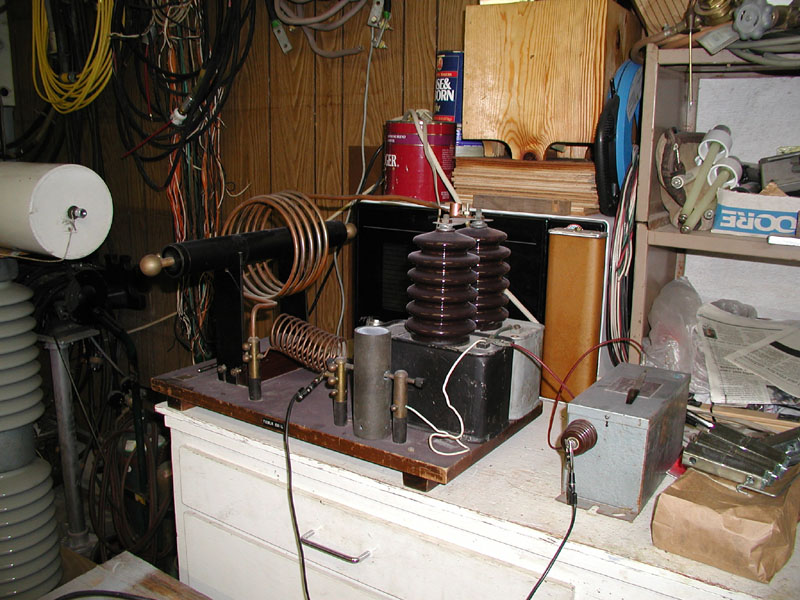
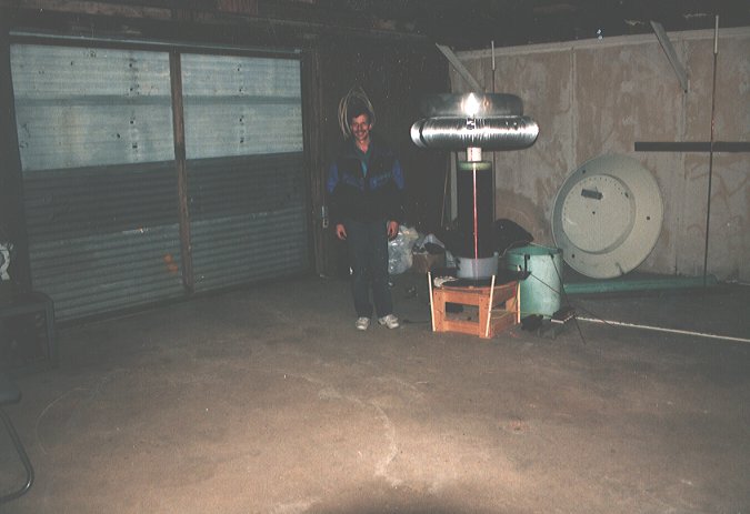
This is the main TCBFW Laboratory. You can see thousands of lbs of assorted HV gear under the carport. The workshop is equipped with all manner of high voltage devices - a true high voltage hobbyists' dream! The workshop in the rear houses the Warthog and is equipped with shielding to help contain the havoc that the Warthog so happily creates. Although this lab sports many tons of HV goodies, it is only one of 4 facilities spread across the greater Ft Worth area. |
|
|
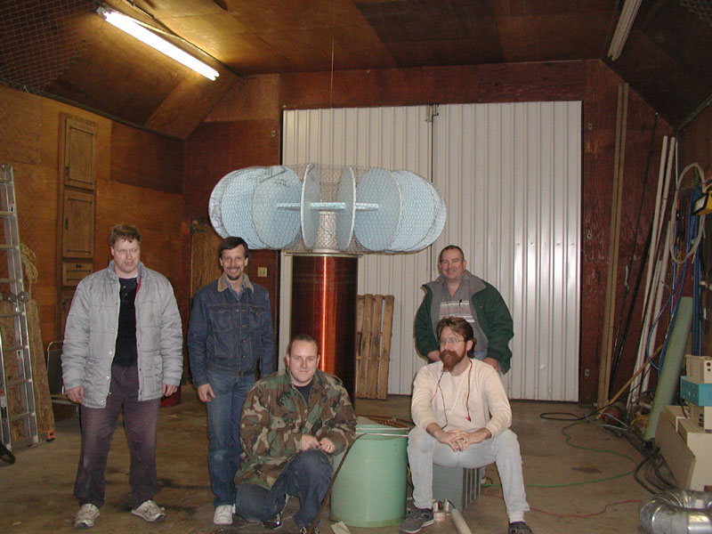
The TCBFW team (& me). From left to right you can see - Max Hempel, Bill Emery, Ross Overstreet, Bert Pool (standing), and Phil Rembold (sitting). Norm Wootan is not pictured. |
Small to Mid-Sized Tesla Coils
|
|
Max Hempel's Coil
|
|
|
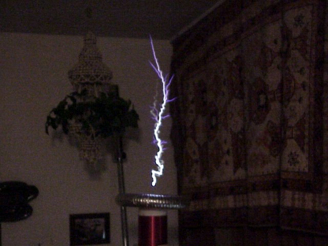
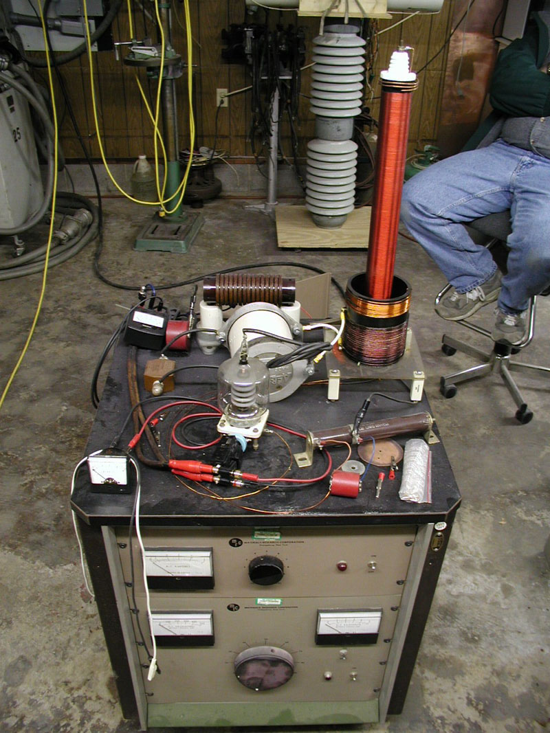
Ross Overstreet's Small NST powered Coil
|
|
|
Another shot of Ross' Coil along with the power controller for the Warthog
Bert Pool made a page from the pictures taken during my February Visit. It has some good pics of my coil along with an excellent pic showing what happens when a neon indicator light catastrophically fails an inch from my hand! See http://users.ticnet.com/bertpool/Ross_O.htm |
|
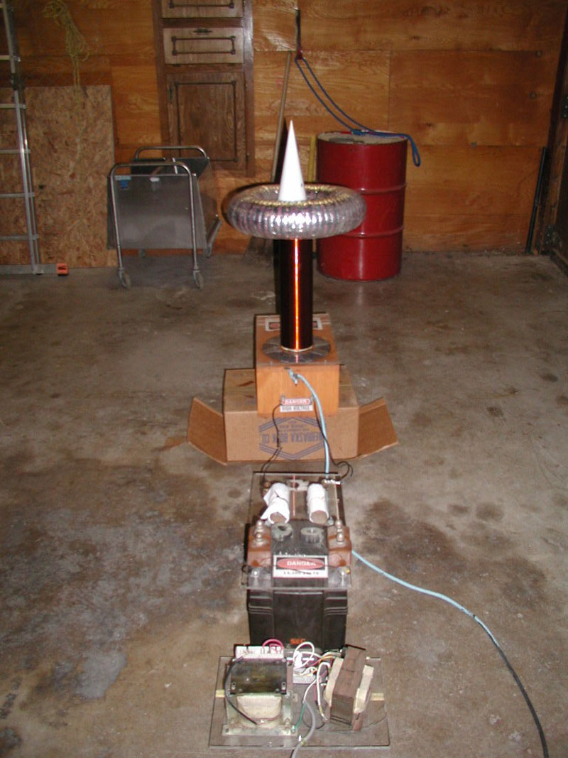
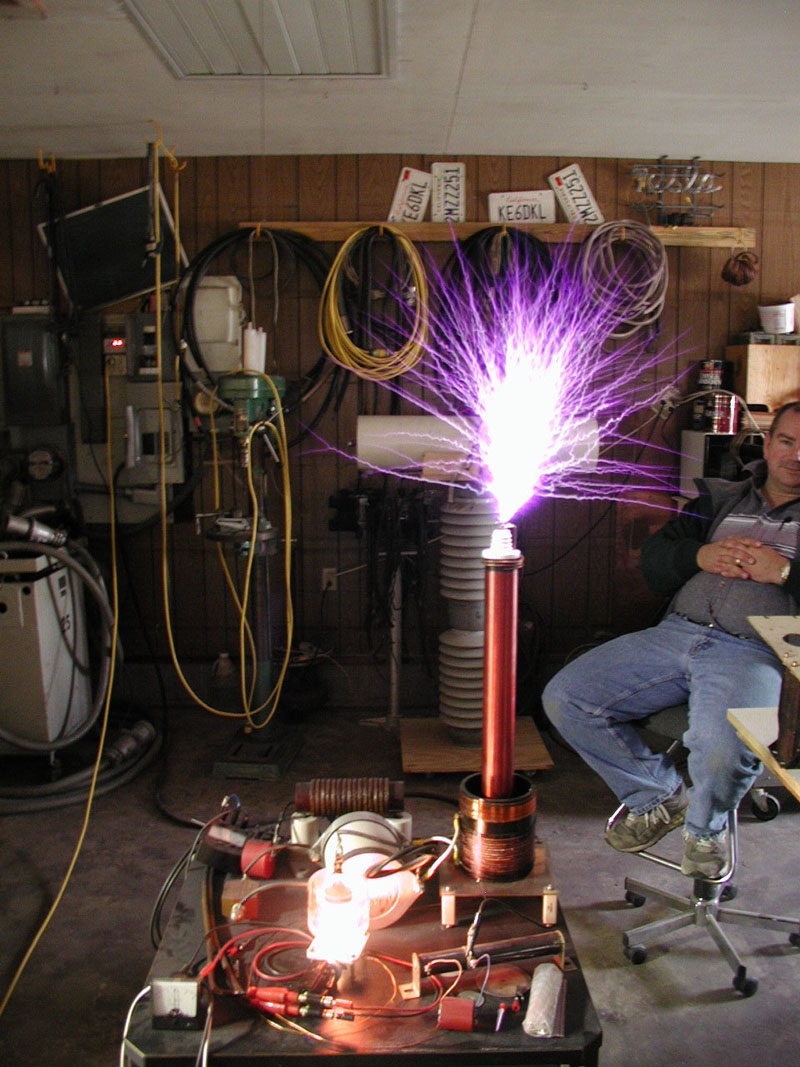
Wild Bill's Beginner Coil!
Text directly copied from an email from Bill "Here is the Rattler coil running at 6 and 7 kw making 7 to 8.5 footers. The one hitting the left side of the shop door is 8.5 feet. I have a whole role of pics and when it ran at 7 kw, it hit over there every time. The tube is 10 inches in dia. and has 30 inches of tight winds of 22 ga wire on it. It was running on .033 uf of cap that was home built. A flat poly plate cap in miner oil. I still have it. It had a three foot home built top on it with a 30 inch smooth spun toroid on top of that. I paid $300 for it back then. It had 13 turns of RG214 silver braid coax for the primary. In a five min. run it would get hot but when I built a flat plate one for it that did not get hot, it did not run any better! It always blew out light bulbs when it ran too, never figured that out.... But I give Richard Hull the credit for getting me in the ball park with the ideas for coiling efficiently! I use to make 6 to 6.5 foot sparks in my old house with it! I kicked out the walls between the bedrooms to run it. Since it was a support wall, I put a 4 inch dia. pvc pipe there to hold up the roof. When it ran you had to stand behind the ground poles and the screen wire to be safe. No one including Bert Pool liked to come watch it run cause there was a water bed that kept you from getting far from it. You were always inches from getting hit. I just thought at the time that was coiling! I started a fire in the attic with it once and had to put it out to keep from burning down my house! I was Stupid. Good thing I am not stupid any more :)" |
|
|
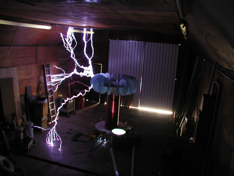
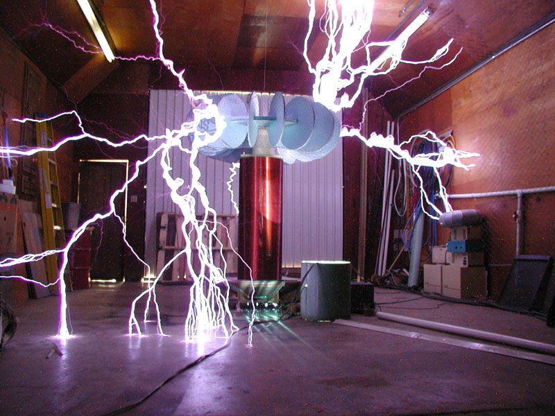
Ladies
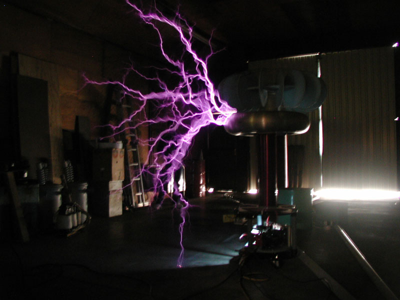
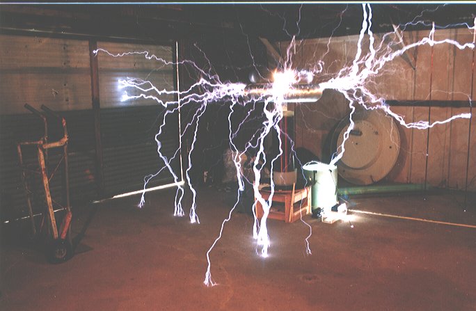
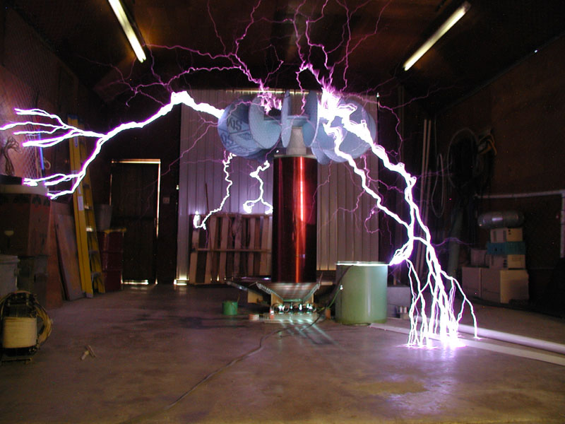
and Gentlemen - I present to you... THE WARTHOG
These images were taken with an Olympus C-3000z in automatic mode. The camera chose an exposure time of 1s and an aperture setting of 3.6. Unfortunately, I forgot my tripod at home and had to hold the camera by hand - this accounts for the slight motion blur. Most of the arcs in the photo range from 8 to 12 feet in length. This set of images were taken during the day as the bottom of the door demonstrates. |
|||||||||
|
Feb 11, 2001 Vistit
|
|||||||||
|
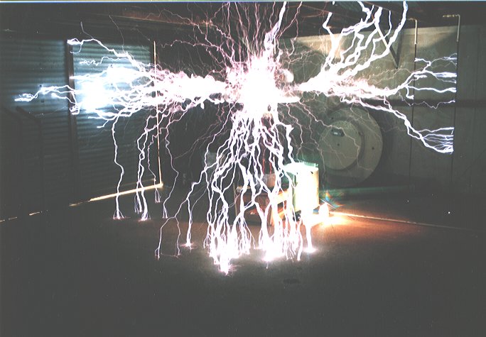
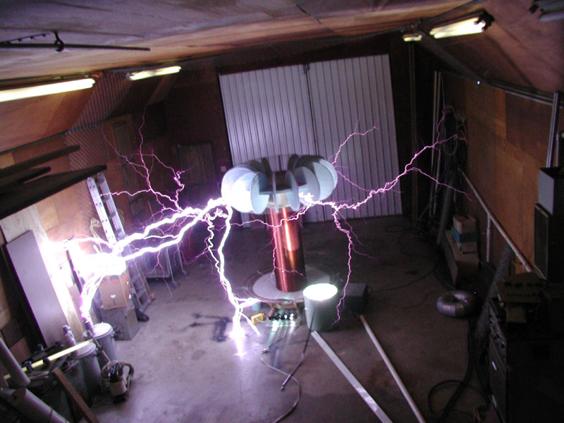
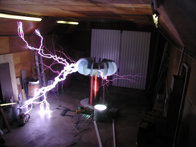
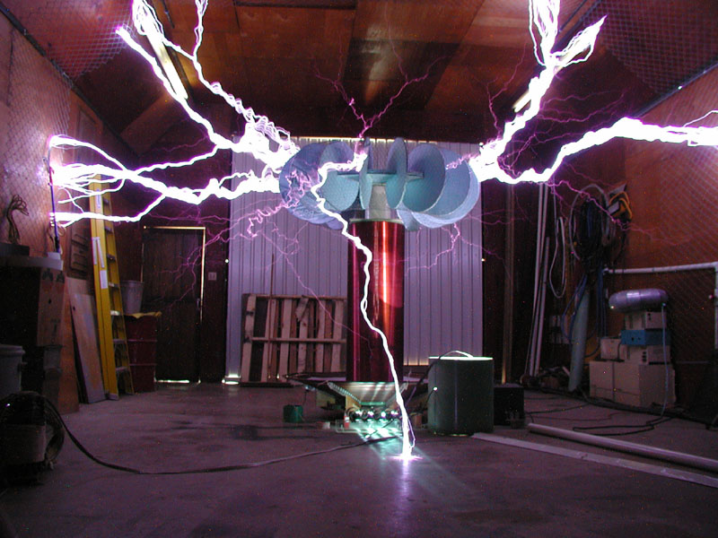
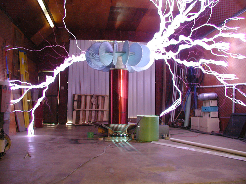
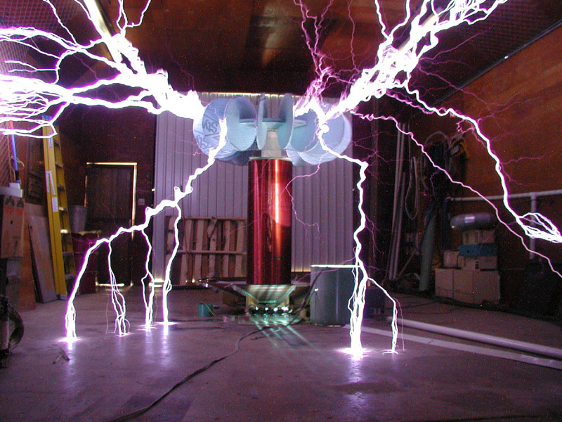
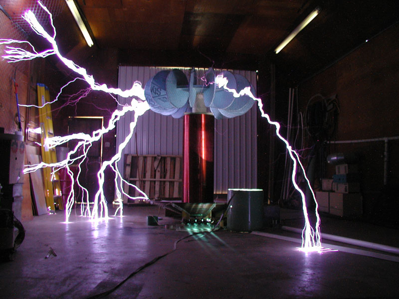
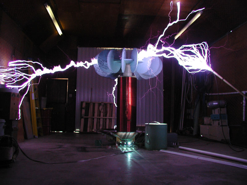
June 2, 2001
Visit
This
trip turned out really well! The Warthog ran better and I managed to
operate my camera a bit better. All pictures were taken with my
Olympus C-3000z in 2048x1536 mode. I set the camera for F2.8, manual
focus, and time exposures from 2 seconds to 4 seconds. It's
important to note that the workshop was pitch black and the only light was
provided by the arcs. The arcs from the Hog are flashbulb
bright! |
|||||||||
|
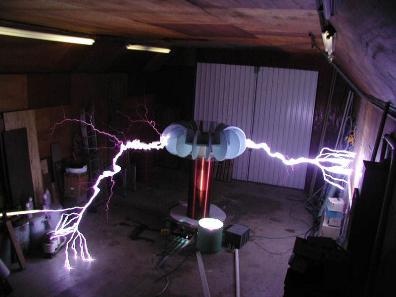
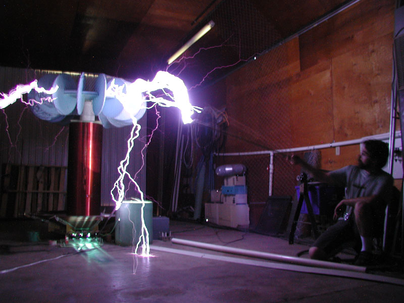
June 2, 2001 Visit - The Kevorkian Experiment!
Wild Bill, Bert and I discussed the consequences of
using a grounded rod to attract arcs from the Warthog.
|
| Phil
Rembold's VTTC
|
|
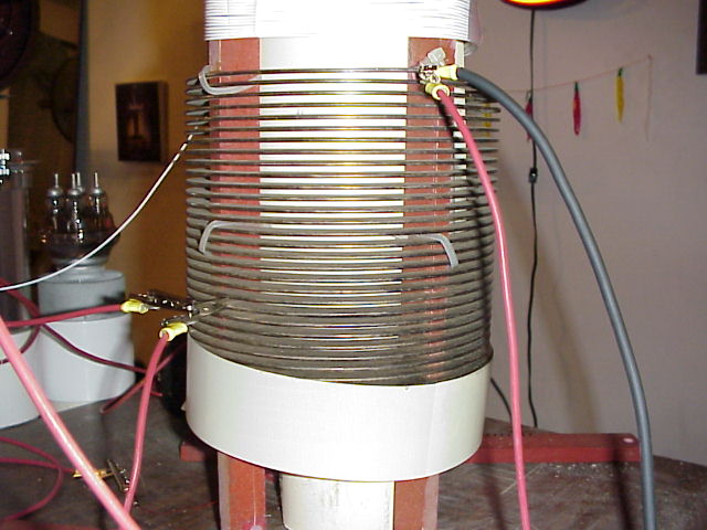
Wild Bill Emery's VTTC
Bill has been working on VTTC since my last visit. Here are a few pics and some quoted text from an email "Here are the pics of the thing running with 2 footers coming out of it for a long time, for a tube coil. I think I need to re-design it to make it more efficient. It is running at .8 amps at 6 kv ! Had to really put the power to it to make it come out like I wanted, and it still sucks! At 2.1 kw I get 17 inches, but to get two feet it must run at 4.8 kw !" Bill is using a silver plated copper ribbon helix for his primary. You can see the three triodes in their respective "sockets" in one of the pics. This allows Bill to quickly switch between triodes for experiments. |
|
|
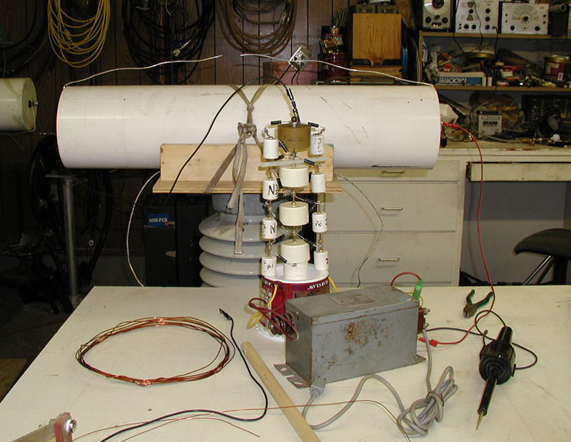
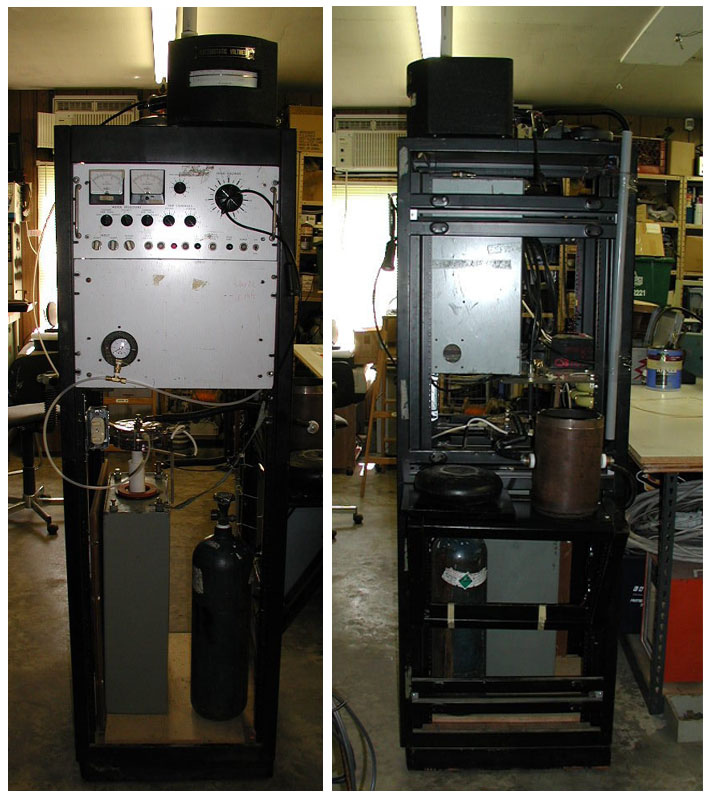
This is a 100KV, 0.4uF capacitor that is being
charged by a 15KV/30ma NST through a 5 stage Cockcroft Walton Multiplier
(CWM). The CWM takes the 7.5KV from
each bushing on the NST and turns it into about 50-60KV before feeding the
capacitor. The diodes on the CWM are 12KV, 333ma microwave oven
diodes. All capacitors in the CWM are 40KV with the center stack
being 2200uF and the other stacks being 700uF each.
Do you spot the fatal design flaw here? We don't have any resistance between the large pulse cap and the charging circuit. The fast current reversal during the triggering of the airgap destroyed most all of the diodes in the CWM. Jim Lux's Website has good design information on Cockcroft-Walton Multipliers |
||||
|
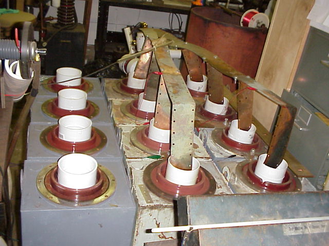
Phil Rembold's Pulse Discharge Rigs
Ton-O-Fun Specs: Portable Rig Specs: Misc Details on the stuff
that we shattered with the Portable Rig: |
|||||
|
|
Wild Bill's Pulse Discharge Rig This shows Bill's bank of (12) 3.3KJ pulse capacitors. It is being dumped through a home made field distortion gap that is a combination of ideas gained from the Maxwell gap and his own design. The gap works reliably between 40 and 50 KV at its current setting. This is possibly the most dangerous machine that I have ever seen! My pulse quickened as I watched the needle on the electrostatic voltmeter swing between 60 KV (power supply voltage) and 45KV (bank target voltage). Everything seemed alive with corona. The resulting explosion when Bill hit the fire button was nothing like I had ever seen before. When a TCBFW member tells you something... Listen to them. Case in point - Bill explained to me that he needed to stack a minimum of 250 lbs on top of the lid of his pulse-discharge containment. I said "yeah, right" and smirked as he placed (2) 70lb sandbags and (3) 15/60 NSTs on top of the steel lid. Upon hitting the FIRE switch, the lid of the containment lifted enough for a handful of wire frags to spew forth into the lab! |
||||
|
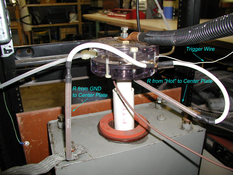
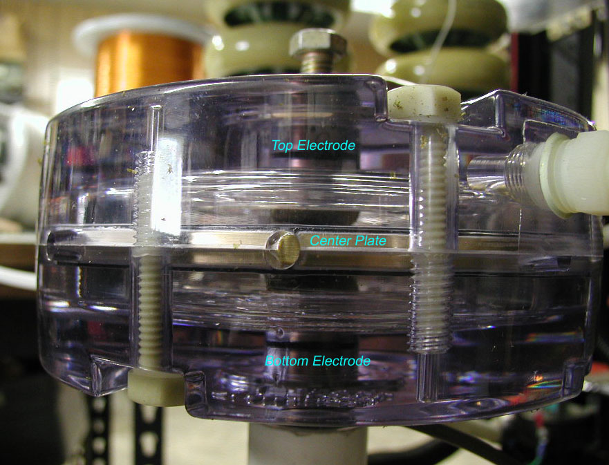
Bill's "Maxwell Clone" Triggered Spark Gap
TEXT AND PICS COPIED FROM AN EMAIL FROM WILD BILL TO ALAN YANG Hi Alan, here are pics of the big switch thrown together in an 8 inch drain pipe, don't let the simple picture fool you. This weighs 18 lbs. and has a center disc 1/4 inch thick in it with 2.5 inch electrodes. Try finding the plate in copper to make it out of and then cut it to size.....the plate takes the brunt of the arc on the way by. Put a pulse on the center disc, and it arcs to one side and triggers the gap. The higher the voltage, the more the tolerance on the gap, and the less prefires. For magical reasons, there are always prefires, although I have not had one at 50 kv in over 30 shots!! Also I put pics of the 40 kj pulse circuit and the smaller high voltage switch. That size switch will explode at 15 kj with 12500 volts! At 50 to 60 kv, it will take 25 kj all day long......And if you will notice, I had to doll up the switch with balls etc. to hold in the 60 kvdc. Also you will notice I had to put the 100 meg bias resisters in plastic, and I put the pulse cap to trigger it in plastic also. And I had to go to a battery operated trigger circuit cause I blew up every plug into the wall thing I had, (the battery charger, my 10 amp supply, two of them, etc . etc. ) And in the teflon tube is a one meg resister that is 2 inches dia. by 16 inches long. And the bucket under the table has bypass in it to protect the diodes in the 10 kw z-ray tranny. And there is the hot tub sized 60kv electrostatic meter, which happens to be a voltage standard. |
|||||
|
DANGER -
DANGER - DANGER - DANGER - DANGER - DANGER - DANGER - DANGER - DANGER -
DANGER - DANGER - DANGER |
|||||
|
|
Bill did a quarter for me at 18.5 KJ @ 50 KV. The quarter is actually considerably longer than it is wide now. It has cracks on each face where some of the copper vaporized and blew through the ends! |
||||
Other High Voltage / Vacuum Projects
|
|
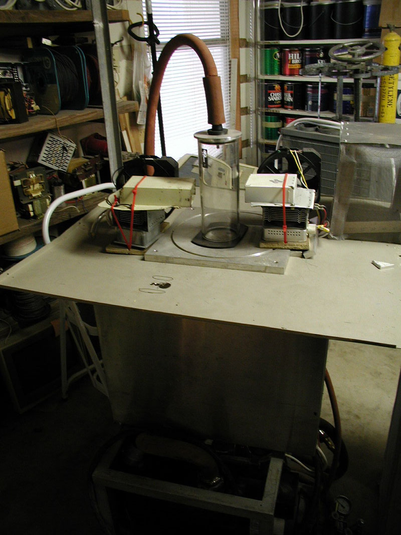
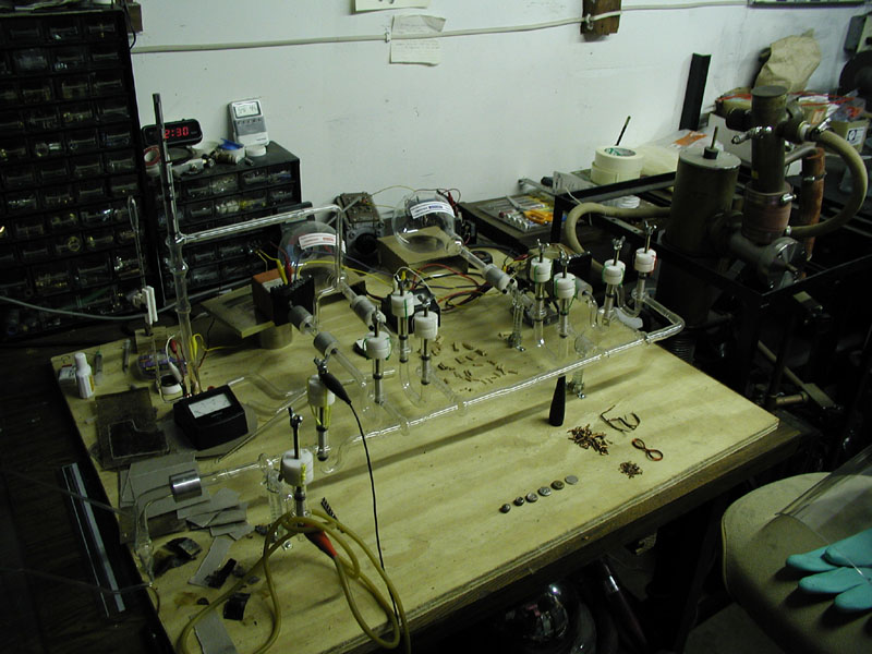
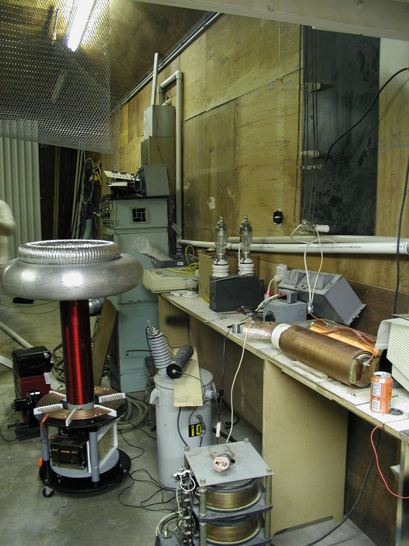
This is an interesting device that, frankly, scares the
living hell out me (i.e., it's really cool!). I can't reveal its
entire purpose but I can tell you a little about what it does. The
devices on the on each side of the glass tube are magnetrons from
Microwave Ovens. The glass tube is connected to a vacuum pump.
A manifold is attached to the bottom of the platform that allows various
test gasses to be passed into the chamber and circulated. Upon
achieving the proper mixture of gas in the chamber at the proper pressure
the magnetrons are switched on and a super hot ball of plasma appears in
the center of the chamber. Bill has designed a faraday cage to go
over the top but it apparently leaks pretty bad. Bill's words of
wisdom - "Distance is your Friend!".
More info may be made available about this device by TCBFW after further research. |
|
|
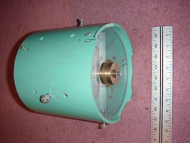
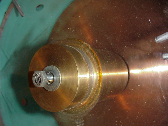
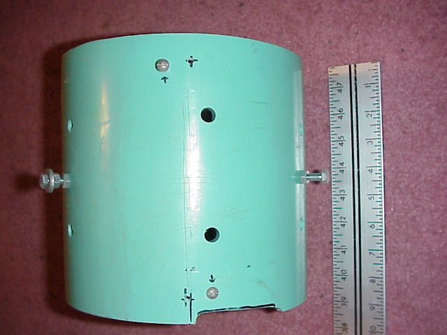
Bill built this a custom vacuum manifold for his small Neon Sign business. New systems cost between 3,000 to 5,000 dollars and Bill was told that it was not practical to attempt one of these at home. Bill's system now out performs the professional system at a local Neon shop. You gotta love it when the amateur scientist proves the "experts" wrong <grin>. The system can attain an ultimate pressure of around 10^-4 torr on just the rotary vane pump and can get down around 10^-7 torr once the diffusion pump kicks in. Bill has equipped the system with capacitive vacuum gauges to accurately measure the pressure. |
I express my deepest
gratitude to Phil and his lovely wife Venice for their friendship and hospitality.
The TCBFW are all great guys, build incredible gear, and really know how to have
a good time.
[ Ross-O's Main Page
| TCBFW Main Page | Contact
Ross | Contact Phil
of the TCBFW | Bert
Pool's Website ]
� 2001, Ross Overstreet


.jpg)