High Voltage Power
Supply Units
Popular
Tesla Coil PSUs
Coilers use a wide variety of HV
PSUs. Here is a quick summary from smallest to largest.
Currently, this page will only go into detail on NSTs. More PSUs will be
covered here as I gain experience.
OBIT - oil burner ignition transformer,
puny
MOT - microwave oven transformer, typically voltage is a little low and you have
to make series/parallel connections
NST - neon sign transformer, ideal for coils with up to 5 ft arc output, easily
damaged by TC service
PT - potential transformer, requires ballast circuitry
PIG - distribution transformers like the ones you see on light poles.
Most coilers use 5-20KVA, 14KV units. Requires ballast circuitry
Neon
Sign Transformers (NST)
 |
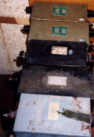
This is what you might find
at your local Sign Shop
I just got my hands on these 60 ma
NSTs. I found them at a small shop that makes Neon Signs and does sign repair in
general. From many months of searching I found that small shops are the best and
DON'T rely on phone calls.
There are basically 4 types of NSTs - you have 12KV models and 15KV models. Each
voltage comes in either 30ma or 60ma. Look for the 60ma models, but don't pass up
the 30's. Richard Quick has an excellent article on all aspects of NST usage.
I will look for it and link it here.
Richard
Quick Article on NSTs
This article covers depotting! I'm an order of magnitude more
agressive than Richard when It comes to increasing current output, but he is
trying to build a reliable device and I'm just playing around on the upper
limits of performance in the name of experimentation. Remember, many NSTs
die at their normal operating current (much less my 200+ ma!).
|
Enhancing
an NST
NSTs are current limited
transformers. This means that a NST will only produce a fixed amount of
current regardless of the output load. The current is limited by using
packs of metal shunts to "short circuit" the flux from the primary and
prevent it from intersecting the secondary. The current limit may be
adjusted by adding or removing individual leaves in these shunts. The
following pics are probably much more helpful than my ramblings...
All pics are
"clickable"
 |
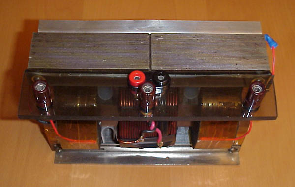
Final version
Final version of
the NST enhancement. Note the acrylic "C" shaped parts
that completely wrap around the secondaries. I also coated the edges
of the secondaries with about 2 coats of clear epoxy. Testing shows
that these additions, with the additional precaution of reducing my input
voltage to 120V, eliminates all of the nasty flashover and corona problems
that I was having.
|
 |
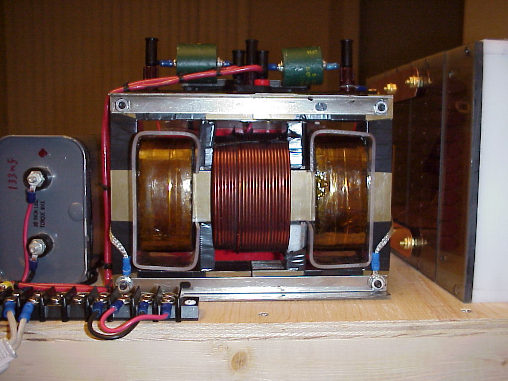
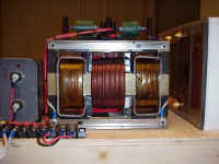
Here is a Franceformer
12KV, 60ma unit after LOTS of work. The primary is the heavy gauge
coil in the center. The secondaries are wound on each side.
You can see the HV end of the secondaries going off to the banana binding
posts on the plexi and you can see the ground end of the secondaries
running out to a bolt on the E core.
The shunts are located on each side
of the primary and contain about 8 leaves each in this photo. I have
the shunts held in with some scraps of LDPE for testing and photos.
I need to investigate a more secure way to hold them in place for actual
TC use.
Note the insulative tape wound on
each side of the core nearest the secondary. I need to revise the
insulation to include the top and bottom of the core as well, occasionally
an arc will creep along the surface of the tape to the core! Note
this configuration is for photo/educational purposes only. Flashover
and corona were severe when operated in this configuration. See
"final version" photo above |
 |
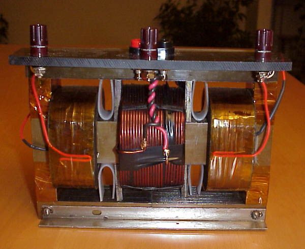
This is a top view
showing the primary connection, 2 HV connections, and the ground
connection in the center. Note that the core is composed of (2) E
shaped sections that are held together by 4 bolts on the corners.
There is no weld in the seam so you can easily seperate the halves and
remove the primary and secondaries. Note
this configuration is for photo/educational purposes only. Flashover
and corona were severe when operated in this configuration. See
"final version" photo above |
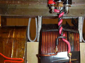 |
Close-up of the shunts. Note
this configuration is for photo/educational purposes only. Flashover
and corona were severe when operated in this configuration. See
"final version" photo above
|
Revision B (see
previous work below)
Although I couldn't get it to
arc over at 140V input open circuit, it displays some rather nasty flash-overs
when integrated with the RC filter and spark gap. The flash over usually
occurs when trying to ignite the gap. I coated both the inboard and
outboard edges of the NST secondary coils with epoxy. I made some acrylic
"C" shaped parts that wrap around the secondaries. The NST
originally had a tar paper version of this when it was potted.
I decided to stick with lower
voltages and run the NST at its rated input. I rewired my control box to
only supply 120 VAC. I adjusted the shunts in the NST to allow for about
200ma at the lower 116V input voltage. Between the lower voltages and
better insulation, I hope that cured the flash-over problem.
Here is the new test data
| Vin (volts) |
I in (amps) |
I out (ma) |
| 48 |
6.5 |
50 |
| 60 |
9 |
75 |
| 72 |
13.5 |
100 |
| 84 |
18.5 |
125 |
| 95 |
22 |
150 |
| 106 |
25 |
175 |
| 114 |
26.5 |
197 |
Vin was measured with a Wavetek 27XT. (I out) was
measured with a Simpson 200ma analog meter. (I in) was measured with the
cheap current meter on my control box. It's not very accurate but is handy
in showing a trend. My output current goes up to a solid 200ma and the
input current drops to 20.5A with the addition of the 135uF PFC cap.
Revision A (see
previous work below)
The original configuration
displayed occasional flash-over problems when running the variac at settings
above 120V. Had a problem with the NST HV bushings arcing to an angle
bracket used to support the plexi deck. I removed the angle bracket.
I removed the Kapton tape from the sides of the E core and replaced it with
electical tape and scraps of PE from a milk jug.
Preliminary testing of the de-potted NST
Voltage Input was 134-136VAC
from my controller
Input
Current |
Output
Current |
# of leaves
per shunt |
| 13.5A |
107ma |
14 |
| 17A |
128ma |
12 |
| 19A |
150ma |
10 |
| 22A |
175ma |
8 |
| 30++ A |
300ma |
0 |
Results of adding a 135uF PFC
capacitor to my ENST on the "8 leaves / shunt" setting
Note that the PFC cap almost halved the imput current while giving me slightly
more output current.
I believe that the gain in output current happened b/c the input voltage rose a
bit with the lower current demand.
Input
Current |
Output
Current |
PFC Value |
| 22 A |
175ma |
0 uF |
| 14.67A |
180ma |
135 uF |
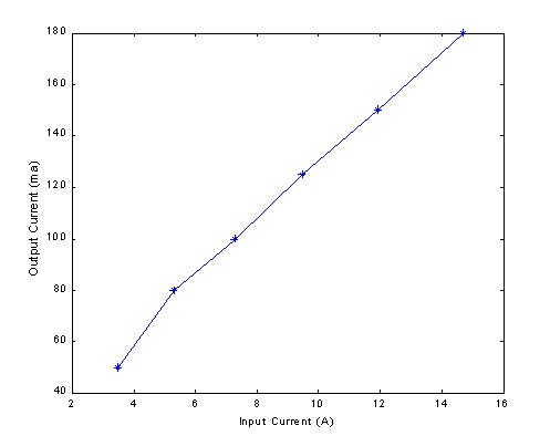
I wanted to check for
saturation of the NST core at higher power levels.
Saturation should be evidenced by a steep increase in input current with respect
to output current.
The NST has 8 leaves in each of the 4 shunts and is equipped with the 135uF PFC.
| I
(in) |
V (in) |
I (out), ma |
| 3.5 |
65 |
50 |
| 5.3 |
75 |
80 |
| 7.27 |
95 |
100 |
| 9.48 |
110 |
125 |
| 11.92 |
120 |
150 |
| 14.67 |
120 |
180 |
If you plot Output Current vs
Input Current, you get a nice linear relationship.
This suggests that saturation is not a problem at this power level.
[ Back to Tesla Main
| Back
to Ross Home ]