How to Tame a Wild MOT
I was well satisfied with the performance of my original twin MOT power supply with voltage doublers. The thing pushed some big, ugly sparks out of my new & improved junk box coil. However, the twin MOT beast had at least one serious drawback. It sucked too many amps from the wall outlet, requiring me to wire it for 240vac. Our cousins in 50Hz land may not understand the problem, since 240vac is the normal residential voltage "over there". But for us Yanks, 240vac is reserved for only a few, heavy duty applications such as electric ranges (cookers), window mounted air conditioners, clothes dryers, and perhaps a single 240vac outlet in the garage for that arc welder or big air compressor. Most American homes have very few 240vac outlets and many apartments and condos have none at all. 120vac at 15A or 20A is the norm for 99% of USA household outlets. I had the foresight to wire my garage with a 240vac/50A welder outlet plus a 240vac/20A outlet for a window unit air conditioner. These made it easy for me to feed the twin MOT beast, but left many of my fellow hobbyist unable to emulate my MOT PSU success.
Another drawback to the original twin MOT monster was the lack of adjustability. It was stuck permanently at full-throttle, in the neighborhood of 3KVA or so. When I decided to reconstitute the twin MOT PSU, I made some changes. My goals were adjustability for different power levels, and optional 240vac or 120vac operation. Fortunately, I didn't have to blaze this trail from scratch. I had experimented with high voltage-side capactive ballasting when I was building my original MOT PSU, but I had abandoned the idea due to erratic results. Later however, a poster on the Tesla coil mailing list related how he had used series capacitive ballasting on his own level-shifted twin MOT PSU with good results. This gave me hope that I could make it work also, so I thought I'd have another go at it.
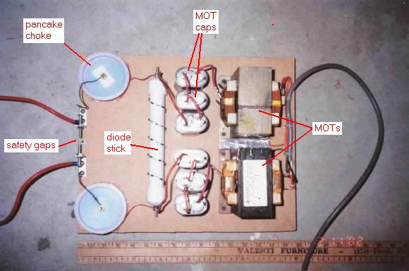
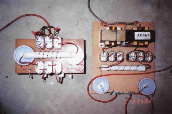
I decided to stick with the time tested half-wave voltage doubler circuit, just like the one employed in the microwave oven itself. I built the MOT PSU breadboard-style, on a small sheet of 1/2" high-density fiberboard. I used a nearly identical pair of MOTs that I believe are both from SHARP "Carousel" ovens. I'm reasonably sure they are both rated at 2100vac (open circuit) and 750ma (short circuit). Contrary to popular belief, MOTs are shunted and have some internal current limiting. The MOTs I'm using, for example, read about 750ma when the secondary is shorted with an ammeter. They hum a bit and overheat quickly in this condition, but they do self-limit. But I digress. Back to the circuit. The main change I made was to put three voltage doubler caps in series on each high voltage leg, for a total of six caps. I made up some short jumper wires which permit me to use all six caps in series for about 1080VA, four caps in series for 1600VA, or only two doubler caps for about 3200VA. The low and medium power settings can run from a 120vac outlet. The highest power setting still requires a 240vac outlet rated for at least 13A.
I breadboarded the MOTs, a stick of twenty four, 1N4007 diodes in series, two 1000pF/10kv ceramic disk caps for bypass filtering of the diodes, and a couple of output chokes. I soldered all the diodes together in a single string, then coiled them around a short length of 3/4" PVC pipe. I soldered the two ceramic disk caps in series and slipped them inside the pipe the diodes are wrapped around. Electrically, the diodes and caps are in parallel. The only purpose of the little ceramic disk caps is to allow any RF leakage from the Tesla coil to bypass the diodes, possibly sparing them from RF destruction. I have no measurements or data to back up the need for this filtering arrangement--it just seems like a good idea.
In the original twin MOT supply, I used 100 Ohm, 55W power resistors on the output for RF filtering. Unfortunately, I burned up the resistors during my ridiculous Marx coil experiment, and never got around to replacing them. To avoid buying new power resistors, I elected to wind some output chokes. I used 3" plastic "test plugs" from Lowe's. These are used to temporarily plug the end of 3" PVC pipe for leak testing of sewer systems during construction. They are very cheap and appear to be made of polystyrene. I drilled holes through their centers and put a brass screw through two of them to make a bobbin. The two plastic disks were spaced apart with only a single brass hex nut. I soldered the end of a 28AWG magnet wire to the spacer nut, then tightened the whole thing together with only a single nut on the outside. I chucked the bobbin into my hand drill, and just spun the wire on. I estimate it took 750-800 turns to fill them up. On the outside of the bobbin, I spun on another 50 turns or so of 22AWG plastic insulated hookup wire so I wouldn't have to try to make connections with the flimsy 28AWG wire. I stuck these little pancake chokes to the breadboard with silicone glue. The MOT caps and diode stick are also glued down with clear silicone adhesive.
In NST-based Tesla coils, the RF filter is considered a discrete, separate circuit. However, in my design, the RF protection filter and the voltage doubler circuit are integrated into a single doubler/filter. Likewise, the safety gaps to AC ground seem to be in the wrong place. Conventional wisdom says they belong right after the transformers. I put the safety gaps right after the transformers in my original MOT supply, and found that the doubler diodes burned out every time they fired! Since the diodes, and not the MOTs, are the most sensitive part of the power supply, it makes more sense to use them to defend the doubler circuit. The safety gaps work fine where they are now, and they do fire every few seconds, which tells me they are doing something useful.
Initial testing was at minimum power, with all six MOT caps in series for about 1080VA. I test fired it on the new & improved junk box coil, and was very pleased with the performance. The sound of 60Hz pulsed DC is distinctive, and kind of disturbing. It sounds like an ax being sharpened with a bench grinder--a real harsh grating noise. My perpendicular air blast gap is only good for short runs, as the heavy current starts power arcing within less than a minute. I suppose I'll have to go back to a sucker gap arrangement if I want to do long runs. Running at 1080VA or 1600VA doesn't seem to stress any of the PSU components. The diodes and chokes remain at room temperature. The MOT cores warm up a little at 1600VA, but not enough to be worrisome. I was so pleased with the outcome of the breadboard model MOT PSU (which I was really building for fellow coiler Robert Even Teet), I decided to make one for myself.
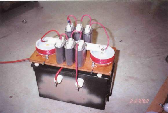
I used my original MOT twins immersed in motor oil in a military surplus .30 caliber ammo can. I wanted a smaller footprint, so I squeezed the MOT doubler/filter circuit onto a tiny plank of 1/2" fiber board so I could stack it on top of the MOTs. This required a bit of creativity with component layout, but I made it all fit. I tested my new, compact model MOT PSU with a 240vac power cord, thus verifying the design is truly dual voltage.
I think the new power supply is more versatile and more useful than the original twin MOT supply. The 1080VA and 1600VA settings are much easier on caps and gap, and the footprint of my compact model is similar to that of a 60ma NST. I could even package my MOT PSU on the bottom deck of the Tesla coil if I wanted to. I'm well satisfied with the "tamed" MOTs, and I plan to make this my standard medium coil power supply. Impoverished coilers of the world unite--you have nothing to lose but your NSTs! (Scroll down for pictures, FAQ, diagram, etc.)
P.S. If anybody out there builds or has already built a twin MOT power supply similar to mine, I'd like to hear about it and possibly see some photos? I'd like to know about successes as well as failures.
-GRH-