Technological background, part#2
(or 'how to produce your own indoor lightning')
Elements of a TC:
|
 |
|
| How to calculate a TC "from bottom up" | ||
1" = 1 inch = 25.4 mm
1 mil = 1/1000 inch
1 foot = 12 inch
1 mm = 1/10 cm = 1/1000 m
1 CM = 1 Circular Mil = (1"/1000 * 0.5)2 * Pi = 0.5067 *
10-3 mm2 = area of a circle with 1 mil diameter
|
 Click to see the full size of the image. |
| * concerning the line filters (and grounding in general):
http://www.pupman.com/listarchives/2000/December/msg00810.html
Subject: Re: EMI filter hookup <SNIP> I don't know about pro and cons of "backward" connection, but I can say something about grounding. With my old TC and Thor's DC switching power supply I had this configuration:
Running the coil I had 1/2" CONTINUOUS sparking between table and tank rack, even if both of them were grounded to the SAME POINT by 5' length of copper sheet! So there is no doubt: you have such transients on the TC ground, that even a very low inductance connection will result in generating a (relative high) potential on the TC ground path and even on the grounding point. With the EMI filter you want to protect the mains phase and neutral from potentials too high in respect to the plug (3rd wire) ground. That ground is definitevely NOT your TC RF ground. If you connect the EMI filter GND to the RF ground (I.M.H.O. :) ) you'll possibly achieve nothing or just a damage. The RF GND is practically floating to a potential driven by transients and its own (even if low) impedance.
To limit the potential on plug phase and neutral, I believe you
must connect the EMI filter GND to your plug (3rd wire), that is:
Some more remarks on line filters and grounding: |
Remark: The xfmr-core should be grounded to the plug-gnd IMHO!
P=1/2.Cprim.Û2.bps |
In this equation, Cprim is the capacitance of the main capacitor
in the tank circuit. Û is the peak voltage applied to the high voltage
capacitor (determined by the gap setting of the main system spark gap or
the safety gap). And bps is the number of "breaks per second" and says how
often the main spark gap shorts and delivers the power to the primary coil.
Of course, the high voltage xfmr must be able to charge the cap to the peak
voltage bps times per second. This means, it has to have a minimum amperage.
The voltage should be in the range of 6kV-20kV, preferable 6kV-12kV for beginners
coils. Big coils usually run on higher voltages (up to 20kV). This higher
voltage has two major advantages: you need a lower capacitance value and
the performance of the spark gap is better. The disadvantages are that the
costs for the cap explode with higher voltages, the need for a better insulation
requires more thougts on wiring.
Go to my neon page for more info about the most
common xfmrs.
back to the top
P=2*Pi*f*C*U2) decrease
the usable amount of current as well as resistive losses in the damping resistors
(R=Ploss/I2). Of course, the damping
resistance has to be high to be effective. Therefore, the filter board has
to be designed new for every different power level. I myself go for 1% to
10% losses in the filter. This way, I never had a failure in my xfmrs. The
best way is to test the filter board with a function generator hooked up
to the filter output and an oscilloscope hooked up to the filter input. It
is important to connect the HV-xfmr also in this test! If there should be
any resonance peak, one should redesign the filter board.
Î=sqr(2.Ec/Lp)). The RF produces
intense stress on the dielectric of the cap. The voltage can rise above the
peak voltage of the xfmr due to resonance with 50(60)Hz line frequency. For
limiting the cap voltage, a second safety gap (as described under the
filter paragraph) is usually set directly across its
terminals. This cap safety gap always should have a current limiting
resistor in series with a resistance equal to the impedance of the tank
circuit!Z=Uo/Is=1/(2.pi.f.C) |
This formula gives the matched capacitance value. The Uo is the
open circuit output voltage of the xfmr, the Is is the short circuit
current of it, f is the line frequency. This generates a line frequency resonant
circuit between the xfmr and the cap for optimum power transfer. Make C about
120% (up to 160%) of the optimum value for static gaps and up to 240% for
syncronous rotary spark gaps (SRSGs). This approach to use a large cap is
called "LTR" which means larger than resonance, it avoids resonant voltage
rise and give best performance.
A description how I built my caps and some important safety hints can be
found on my cap page.
back to the top
|
||||||||||||
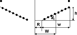
| a is the angle of the coil:
tan(a)=h/w, h is the height of the coil, W n is the average radius
(W=R+1/2.w)at the tap point, w is the "width" at the tap point, n is the number of tapped turns, hn is the height up to the tap point, wn is the "width" to the tap point. |
 |
|||||||||||
| hn , wn and W in inches, L in microhenries. | ||||||||||||
Make at least two additional turns, experience has shown that you'll
need them for bigger top loads! The angle a should be around 30° to
0° for medium or high power coils. Make the connections in the
tank circuit short! At the tap point, the primary should not be wider than
the secondary is tall. The inner turn should have a distance of 1"-2" to
the secondary. Try to achieve a tap point of 4-20 turns for the two extrema
Ct=1/2.Cself up to
4.Cself and primary cap size from 120%-30% of the matched
one (Ct=toroid capacitance and Cself=self capacitance
of the secondary coil, see below for more information on these parameters).
This way you can change components very flexible if you're upgrading your
system (and you WILL upgrade your system someday...). Of course this is only
true 'till you start swapping your static gap against an ASRSG
or SRSG...
back to the top

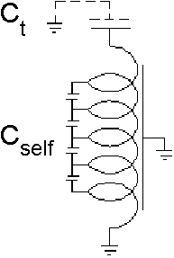
(Schematic image |
The secondary coil itself has inductance and self capacitance. You can
calculate the self capacitance Cself of the secondary coil with
the Medhurst formula:
with d
or you can use the fit formula (valid only for 1 < h/d < 5):
R is the coil radius (=0.5.d), |
Finally you can calculate the natural frequency of the bare secondary coil
with this formula:
f =
1/[2.pi.sqr(L.Cself)] |
With top capacitance Ct, the
frequency of the secondary drops down to approximately
f =
1/{2.pi.sqr[L.(Ct+Cself)]} |
(From the schematic above, you can see that the total capacity of the coil
is not Ct+Cself, but the term is a good
approximation at least for the frequency.)
If you want to build a piece of art, read this text from Richard Quick
on how to build the perfect secondary (highly
recommended though it is a bit outdated!).
back to the top
Ct=(1.28-d/D).sqr[2.pi.d.(D-d)] |
Ct is in pF, D is the outside diameter and d the cross section
(cord diameter) of the toroid in inches. For better shielding, its a good
trick to mount a large toroid above a smaller one (try and error :-). A toroid
can be made from nearly everything: corrugated plastic pipe, aluminium vent
ducting or something else wrapped around a circular disk. Use hot glue and
self adhesive aluminium plumbers tape to stick the thing together and make
the surface conductive. (Tip: plastic is not as fragile as alu vent duct
or styropor. You can also use some layers of any standard tape for smoothing
the surface before you apply the plumbers tape.)
Here are some texts on how to build a toroid from
scratch.
back to the top
